Answers about answering
I've had several people ask how the automatic phone coupler works. Saying "just fine, thanks" only gets me an annoyed look, so I'll share a couple of drawings...

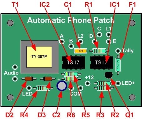
First, a few general points. All of the parts are available from Digikey, but other vendors probably also sell them. There's nothing particularly unique -- no custom-programmed logic or anything like that. Even the DC supply can be an unregulated wall wart. All resistors are 1/4 watt, 5% tolerance. For the sake of the circuit discussion, we will assume that toggle switch S1 is in the center "Auto" position.
Ring voltage (on the order of 90 volts at 20 Hertz) is enough to activate IC2b, but capacitor C1 blocks the DC line voltage. The phototransistor charges up capacitor C2; the combination of R5, R6, and C2 provide a filter that prevents false tripping. When C2 reaches a sufficient voltage it activates IC2a, which switches the phone line into the audio transformer, creating an "off hook" condition and answering the call.
DC current from the phone line flows through the LED of IC1b as long as the circuit is "off hook"; the phototransistor in turn triggers IC1a, which holds the line. When the caller hangs up, the central office briefly drops the DC current, which shuts off IC1, resetting the coupler back to an "on hook" condition. The phototransistor of IC1b is cascaded with switching transistor Q1 in order to provide enough drive current to feed outboard tally equipment.
Setting toggle switch S1 to "Off" essentially shorts out the ring detector IC2b and the line current detector IC1b, preventing the coupler from responding to ringing or holding the line. With S1 in "On", the transformer is hard-switched across the phone line. One nice feature about this is that you can initiate an outgoing call with a phone bridging the line, flip the switch to "On" to activate the coupler, hang up the phone, and then return the switch to "Auto". If the other end hangs up, the coupler will automatically reset. You can also dump the call by switching the coupler to "Off".
One variable you might encounter relates to the quality of your phone lines and the distance from your central office. If you find that the coupler false trips -- especially if it hangs up after a call but immediately re-seizes the line -- try increasing the value of R6. On the other hand, if the front LED just flashes and the phone rings without answering, decrease R6. We have a mix of copper lines direct to the central office and newer lines which come from a fiber rack in our building, and 2400 ohms seems to be a good value that accommodates both.
Finally, zener diodes D2 and D3 prevent spikes on the phone line from zorching your audio equipment or vice-versa. As an aside, you will notice that everything that ties to the phone line is completely isolated from the control logic, and both are isolated from the audio feed.
The whole thing fits comfortably on a single-sided 2" by 3" PC board. It could be somewhat smaller, but I designed this to replace a circuit that used reed relays, and this new board is a direct replacement in the existing enclosures.
Sorry... not very philosophical today.
posted by Jeff @ Thursday, May 11, 2006
![]()
![]()


<< Home